
Regular practice with AP Inter 2nd Year Physics Study Material Chapter 7 Alternating Currents Questions and Answers helps students stay prepared for examinations.
AP Inter 2nd Year Physics 7th Lesson Alternating Currents Questions and Answers
I. Multiple Choice Questions
Question 1.
The r.m.s. value of an alternating current of peak value 10 A is:
1) 5 A
2) 7.07 A
3) 10 A
4) 14.14 A
Answer:
2) 7.07 A
Irms = \(\frac{\mathrm{I}_0}{\sqrt{2}}=\frac{10}{1.414}\) = 7.07 A
Question 2.
The frequency of AC mains in India is:
1) 25 Hz
2) 50 Hz
3) 100 Hz
4) 60 Hz
Answer:
2) 50 Hz
The frequency of AC mains in India is 50Hz.
Question 3.
The power factor of a pure inductive circuit is:
1) 1
2) 0
3) -1
4) 0.5
Answer:
2) 0
In a purely inductive circuit, the phase difference Φ between current and voltage is 90°. Power factor cosΦ = cos 90° = 0.
Question 4.
In an AC circuit, the instantaneous current is given by i – 10 sin(100π t) A. The frequency of the alternating current is:
1) 50 Hz
2) 100 Hz
3) 25 Hz
4) 200 Hz
Answer:
1) 50 Hz
Comparing i = 10 sin 100πt with i = i0 sin ωt, we have ω = 100π
We know ω = 2πf
∴ Frequency f = \(\frac{\omega}{2 \pi}=\frac{100 \pi}{2 \pi}\) = 50Hz
Question 5.
In a series LCR circuit at resonance, the current is:
1) minimum
2) maximum
3) zero
4) infinite
Answer:
2) maximum
At resonance, XL = XC then Z = R. So when impedance is at lowest value, then current is maximum.

Question 6.
The phase difference between current and voltage in a purely capacitive AC circuit is:
1) 0°
2) I leads V by 90°
3) I lags behind V by 90°
4) 180°
Answer:
2) I leads V by 90°
For pure capacitor V = vmsinωt, I = Imsin(ωt + 90°) ∴ Current I leads V by 90°
Question 7.
The reactance of a capacitor decreases with:
1) decrease in capacitance
2) increase in frequency
3) both (1) and (2)
4) decrease in frequency
Answer:
2) increase in frequency
Capacitive reactance XC = \(\frac{1}{2 \pi \mathrm{fC}}\)
⇒ XC ∝ \(\frac{1}{\mathrm{f}}\)
XC decreases with increase in f.
Question 8.
In a purely resistive AC circuit, the average power dissipated is given by:
1) VI
2) VI/2
3) VI cosΦ
4) zero
Answer:
1) VI
In a purely resistive circuit, average power dissipated is P = VI cosΦ.
Power factor cosΦ = 1 ∴ P = VI cosΦ = VI(1) = VI
Question 9.
The power factor of a series LCR circuit at resonance is:
1) 0
2) 0.5
3) 1
4) -1
Answer:
3) 1
At resonance, the phase difference between voltage and current is zero.
Question 10.
A transformer is designed to:
1) increase or decrease AC voltage
2) convert AC into DC
3) increase the frequency of AC
4) store electric charge
Answer:
1) increase or decrease AC voltage
Transformed works on the principle of mutual induction. Transformer is used to change the AC voltage levels i.e, step up and step down, keeping the frequency and power are same.
II. Fill in the Blanks
Question 1.
The r.m.s. value of an AC of peak value I0 is ________
Answer:
I0 /\(\sqrt{2}\) .
Irms = \(\frac{\mathrm{I}_0}{\sqrt{2}}\) = 0.707 I0
Question 2.
The phase difference between current and voltage in a purely resistive AC circuit is _________.
Answer:
0°
In a pure resistor V = vmsinωt, I = Imsin(ωt) ∴ Phase difference is 0°
Question 3.
The power factor of a pure inductive or capacitive circuit is ________.
Answer:
0
In pure inductive Φ = 90° ∴ Power factor = cos Φ = cos 90° = 0.
Question 4.
In an LCR circuit at resonance, the impedance is equal to __________
Answer:
resistance (R)
At resonance, XL = XC. Hence, Impedance Z = R
Question 5.
The average power consumed in a purely inductive circuit is _________
Answer:
zero.
At pure inductor stores energy in its magnetic field during one half cycle and returns it all to the source in the next. The net energy and hence average energy consumed over a full cycle is zero.
Question 6.
The expression for the capacitive reactance _________
Answer:
XC = 1/ωC or 1 / 2πfC.
Question 7.
The expression for the inductive reactance ___________
Answer:
XL = ωCL or 2 π f L.
Question 8.
In a purely capacitive circuit, the current _________ the voltage by 90°.
Answer:
leads
For pure capacitor V = vmsinωt, I = Imsin(ωt + 90°)
∴ Current I leads V by 90°.
Question 9.
In a transformer, the core is laminated to reduce __________ losses.
Answer:
eddy current
In a transformer, the core is laminated to reduce eddy current losses.
Question 10.
The power factor of an AC circuit is given by _______.
Answer:
cosΦ
The power factor of an AC circuit is given by cosΦ
III. One Word Answer Questions
Question 1.
What is the r.m.s value of <111 AC whose peak value is 141 V?
Answer:
Vrms = \(\frac{V_m}{\sqrt{2}}=\frac{141}{1.414}\) = 99.7V ≃ 100V [∵ peak value V0 = 141V]
Question 2.
What is the time period of AC mains in India?
Answer:
The time period (T) of AC mains in India is 0.02 seconds.
∴ Time period T = \(\frac{1}{\text { frequency }}=\frac{1}{50}\) = 0.02s = 20 milli seconds [∵ standard AC frequency in India is 50Hz.]
Question 3.
In which type of AC circuit is the phase difference between current and voltage zero?
Answer:
In a purely resistive AC circuit, the phase difference between current and voltage is zero.
Question 4.
What is the condition f resonance in a series LCR circuit?
Answer:
Condition for resonance: XL = XC i.e., Inductive reactance = Capacitive reactance.
Question 5.
At resonance, what is the value of the power factor in a series LCR circuit?
Answer:
At resonance, the Power factor is 1. Power factor = \(\frac{R}{Z}=\frac{R}{R}\) = 1 [∵ Z = R]
Question 6.
Give the expression for impedance of a series LCR circuit.
Answer:
Impedance Z = \(\sqrt{R^2+\left(X_L-X_C\right)^2}\)
Here R is resistance, XL is inductive reactance and XC is capacitive reactance.
Question 7.
Which device is used to reduce AC without much loss of energy?
Answer:
Step down transformer is the device used to reduce AC without much loss of energy.
Question 8.
Write the expression for power factor in an AC circuit.
Answer:
Power factor cosΦ = \(\frac{\mathrm{R}}{\mathrm{Z}}\) ; R= Resistance, Z= Impedance, Φ is phase angle.
Question 9.
Name the type of current in which electrons flow in one direction only.
Answer:
In direct current(DC), the electrons flow in one direction.
IV. Very Short Answer Questions
Question 1.
A transformer converts 200 V AC into 2000 V AC. Calculate the number of turns in the secondary if the primary has 10 turns.
Answer:
Given Vp = 200 V, Vs= 2000 V, Np = 10, Ns = ?
Transformer ratio formula: \(\frac{N_s}{N_p}=\frac{V_s}{V_p}\) ⇒ Ns = \(\frac{\mathrm{V}_{\mathrm{s}}}{\mathrm{~V}_{\mathrm{p}}}\)Np = \(\frac{2000}{200}\) × 10=100 turns
Question 2.
A pure inductor of 21 mH is connected to a source of 220V, Find the inductive reactance if the frequency of the source is 50Hz.
Answer:
Given Inductance L = 21mH = 21 × 10-3 H, Voltage V = 220V, Frequency f = 50Hz
∴ Inductive reactance XL = 2πfL = 2 × 3.14 × 50 × 21 × 10-3 = 6.597Ω = 6.Ω
Question 3.
What is transformer ratio?
Answer:
Transformer Ratio is the ratio of output emf to input emf of a transformer, (or)
It is the ratio between number of turns in the secondary coil and the number of turns in the primary coil of a transformer.
Formula: Transformer ratio = \(\frac{N_s}{N_p}=\frac{V_s}{V_p}\)
Question 4.
Write the expression for the reactance of (i) an inductor and (ii) a capacitor.
Answer:
(i) Reactance of an inductor is XL = ωL
Here to is angular frequency and L= Inductance
(ii) Reactance of a capacitor is XC = \(\frac{1}{\omega C}\)
Here to is angular frequency and C = Capacitance
Question 5.
What is the phase difference between A.C emf and current in the following: pure resistor, pure inductor and pure capacitor.
Answer:
- In a pure resistor, the phase difference between AC voltage and AC current is zero.
- In a pure inductor, the current lags behind the voltage by π/2.
- In a pure capacitor, the current leads ahead the voltage by π/2.
Question 6.
Define power factor. On which factors does the power factor depend?
Answer:
Power Factor is the cosine of the phase angle (Φ) between the voltage and the current.
Formula 1: P = V I cos Φ. Here cos Φ is called power factor.
Formula 2: Power factor cos Φ = \(\frac{\mathrm{R} \text { (Resistance) }}{\mathrm{Z} \text { (Impedance) }}\)
Power factor depends on the phase difference between voltage and current or equivalently on the ratio R/Z.
Question 7.
What is meant by wattless component of current?
Answer:
Wattless current: In a purely inductive or capacitive circuit, the power factor cos<ft=0 . Then no power is dissipated even though current is flowing in the circuit.
In such cases, the current is said to be wattless current.
Question 8.
Why capacitor blocks Direct Current (D.C.)?
Answer:
D.C. has constant magnitude and direction. Once a capacitor is fully charged, it behaves like an open circuit for D.C. When current passes through the capacitor it blocks direct current D.C.
Question 9.
On what principle metal detector works? Explain it.
Answer:
Metal detector works on the principle of electromagnetic induction.
The primary search coil in metal detector generates an alternating magnetic field. When a metal object is nearby, due to the influence of the magnetic field, current will be induced in the metal. The induced current creates a secondary magnetic field which is detected by the metal detector’s receiver coil, and it generates a sound as an alarm.
Question 10.
How the phenomenon of resonance in the series LCR circuit be used in tuning mechanism of a radio and TV set?
Answer:
In the series LCR circuit, energy alternates between the inductor and capacitor, enabling the radio or TV to pick up a precise frequency. Resonance in the circuit enables radio or T.V. tuning by selecting a specific station’s frequency while rejecting others.
V. Short Answer Questions
Question 1.
Obtain an expression for the current through an inductor when an AC emf is applied.
Answer:
Current through an Inductor with AC emf :
Consider a pure inductor with self inductance L connected to an AC of voltage v = vm sin ωt
Let I be the instantaneous current at any time t passing through the inductor.
Applying the Knchhoffs law on the circuit, we have v – L \(\frac{d I}{d t}\) = 0…………(1)
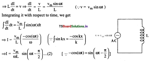
We know amplitude of current Im = \(\frac{\mathrm{v}_{\mathrm{m}}}{\omega \mathrm{~L}}\)
∴ (2) ⇒ I = Im sin (ωt – \(\frac{\pi}{2}\))
Current in an AC inductor circuit is I = Im sin (ωt – \(\frac{\pi}{2}\))
Comparing this with v = m sin ωt, we claim that the current lags the voltage by π/2.
Question 2.
Obtain an expression for the current in a capacitor when an AC emf is applied.
Answer:
Current through an Capacitor with AC :
Consider a pure capacitor C connected to an AC voltage v = vm sin ωt ………..(1)
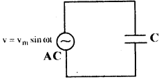
Let I be the instantaneous current at any time t passing through the capacitor.
The potential difference across the capacitor of capacitance C is v = \(\frac{\mathrm{q}}{\mathrm{C}}\) ……….. (2)
From (1) & (2), \(\frac{\mathrm{q}}{\mathrm{C}}\) = vm sin ωt (∵ v = vm sin ωt)
⇒ q = C vm sin ωt
We know I = \(\frac{d q}{d t}\) ⇒ I = \(\frac{d}{d t}\) (C vm sin ωt)
⇒ I = ω C vm cos ωt (∵ \(\frac{d}{d x}\) sinkx = k cos kx)
I = ω C vm sinωt + \(\frac{\pi}{2}\)) ……… (2) [∵ cos(ωt) = sin(ωt + \(\frac{\pi}{2}\))]
We know amplitude of current Im = \(\frac{v_m}{X_C}=\frac{v_m}{1 / \omega C}\) = vmωC
(2) ⇒ I = Im sin (ωt – \(\frac{\pi}{2}\))
Current in an AC capacitor circuit is I = Im sin (ωt – \(\frac{\pi}{2}\))
Comparing this with v = vm sin ωt, we claim that the current leads the voltage by π/2.
Question 3.
Derive the expression for the impedance of a series LCR circuit by using phasor diagrams technique.
Answer:
The Phasor diagram for series LCR circuit is as shown in figure.
Here, voltage VL is in upward direction and voltage VC is in downward direction.
So, net voltage up to point A is VL – VC assuming VL > VC
Maximum voltage is denoted by Vm.
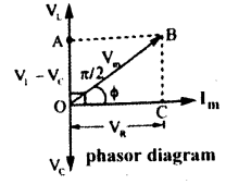
From the phasor diagram, OB = \(\sqrt{(\mathrm{OC})^2+(\mathrm{CB})^2}\)
∴ Vm = \(\sqrt{V_R^2+\left(V_L-V_C\right)^2}\) = \(\sqrt{\left(I_m R\right)^2+\left(I_m X_L-I_m X_C\right)^2}\)
⇒ vm = Im\(\sqrt{R^2+\left(X_L-X_C\right)^2}\)
\(\frac{V_m}{I_m}\) = Z = \(\sqrt{R^2+\left(X_L-X_C\right)^2}\) for XL > XC
This is the expression for impedance of series LCR circuit.
Question 4.
Define resonance in a series LCR circuit. Derive the condition for resonance and explain what happens to current and impedance at resonance.
Answer:
IN RESONANCE LCR CIRCUIT :
An LCR circuit that allows the maximum current at a specific frequency of AC is known as a series resonance (LCR) circuit. Consider an LCR circuit of given frequency n.
At resonance, capacitive reactance (XC) is equal to the inductive reactance (XL).
Thus at resonance XL = XC
Impedance Z = \(\sqrt{R^2+\left(X_L-X_C\right)^2}\) = \(\sqrt{R^2+0}\) = R ⇒ Z = R
Again, at resonance XL = XC ⇒ ωL = \(\frac{1}{\omega C},\) ⇒ ω2 = \(\frac{1}{\mathrm{LC}}\) ⇒ ω = \(\frac{1}{\sqrt{\mathrm{LC}}}\)
We know ω = 2πn ⇒ 2πn = \(\frac{1}{\sqrt{\mathrm{LC}}}\) ⇒ n = \(\frac{1}{2 \pi \sqrt{\mathrm{LC}}}\) Here n is resonant frequency.
Current and Impedance at Resonance:
i) We know I0 = \(\frac{E_0}{R}\)
∴ at resonance if R is minimum then current in the circuit becomes maximum.
ii) At resonance, XL = XC ⇒ Z = R.
Hence if the impedance of the circuit is minimum then resistance also becomes minimum.
Question 5.
What is power factor? Derive its expression in terms of resistance R and impedance Z. Explain its significance in AC circuits.
Answer:
Power factor of an AC circuit is defined as the cosine of the phase angle (Φ) between voltage and current.
Formula: cosΦ = \(\frac{\mathrm{R}}{\mathrm{Z}}\)
Expression: Consider impedance triangle for series LCR circuit as shown in the figure.
Here Z= hypotenuse, base = R, perpendicular = XL – XC and Φ is the phase angle.
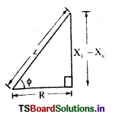
From the right angled triangle .
Power factor, cos Φ = \(\frac{\mathrm{R}}{\mathrm{Z}}\)
Significance: If power factor cos Φ = 1 the maximum power is dissipated in the circuit.
If power factor cos Φ = 0 then no power is consumed. This leads to the concept of wattless current dissipated even though current is flowing in the circuit
Question 6.
State the principle on which a transformer works. Describe the working of a transformer with necessary theory.
Answer:
Transformer: Transformer is a device which transforms AC electric power from one circuit to another. A transformer consists of two coils called primary coil and secondary coil wound on a continuous iron core.
Principle: Transformer is based on the principle of mutual induction. When current in primary coil changes, an induced current is produced in the secondary coil.
Transformer ratio \(\frac{N_s}{N_p}=\frac{V_s}{V_p}\)
Here Ns = number of turns in secondary coil, Np = number of turns in primary coil.
Vs = AC voltage in secondary, Vp = ACc voltage applied to primary,
Working: When an alternating voltage Vp is applied to the primary, the resulting current produces an alternating magnetic flux which links the secondary and induces an emf εs in it. Let Φ be the flux in each turn in the core at time t.
According to Faraday’s laws of induction, the induced emf in the secondary with Ns turns is εs = -Ns \(\frac{d \phi}{d t}\)
The alternating flux <|) also induces an emf in the primary, εp = – Np \(\frac{d \phi}{d t}\)
Here, εs = Vs and εp = Vp
∴ Vs = – Ns \(\frac{d \phi}{d t}\) ……….. (1) and Vp = – Np\(\frac{d \phi}{d t}\) ……….. (2)
Dividing eq (1) by eq (2), we get \(\frac{V_s}{V_p}=\frac{N_s}{N_p}\). This is the formula for transformer ratio.
It there is no power loss, then input power = output power
⇒ ip Vp = is Vs ⇒ \(\frac{V_s}{V_p}=\frac{N_s}{N_p}\)
If \(\frac{N_s}{N_p}\) > 1, then the transformer is called step-up transformer
If \(\frac{N_s}{N_p}\) < 1, then the transformer is called step-down transformer
VI. Long Answer Questions
Question 1.
Derive an expression for impedance oI’series I.CR circuit by using the technique of phasors and deduce the expression for resonant frequency.
Solution:
The Phasor diagram for series LCR circuit is as shown in figure.
Here, voltage VL is in upward direction and voltage VC is in downward direction.
So, net voltage up to point A is VL – VC assuming VL > VC
Maximum voltage is denoted by Vm.
From the phasor diagram, OB = \(\sqrt{(\mathrm{OC})^2+(\mathrm{CB})^2}\)
∴ Vm = \(\sqrt{V_R^2+\left(V_L-V_C\right)^2}\) = \(\sqrt{\left(I_m R\right)^2+\left(I_m X_L-I_m X_C\right)^2}\)
⇒ vm = Im\(\sqrt{R^2+\left(X_L-X_C\right)^2}\)
\(\frac{V_m}{I_m}\) = Z = \(\sqrt{R^2+\left(X_L-X_C\right)^2}\) for XL > XC
This is the expression for impedance of series LCR circuit.
IN RESONANCE LCR CIRCUIT :
An LCR circuit that allows the maximum current at a specific frequency of AC is known as a series resonance (LCR) circuit. Consider an LCR circuit of given frequency n.
At resonance, capacitive reactance (XC) is equal to the inductive reactance (XL).
Thus at resonance XL = XC
Impedance Z = \(\sqrt{R^2+\left(X_L-X_C\right)^2}\) = \(\sqrt{R^2+0}\) = R ⇒ Z = R
Again, at resonance XL = XC ⇒ ωL = \(\frac{1}{\omega C},\) ⇒ ω2 = \(\frac{1}{\mathrm{LC}}\) ⇒ ω = \(\frac{1}{\sqrt{\mathrm{LC}}}\)
We know ω = 2πn ⇒ 2πn = \(\frac{1}{\sqrt{\mathrm{LC}}}\) ⇒ n = \(\frac{1}{2 \pi \sqrt{\mathrm{LC}}}\) Here n is resonant frequency.
Current and Impedance at Resonance:
i) We know I0 = \(\frac{E_0}{R}\)
∴ at resonance if R is minimum then current in the circuit becomes maximum.
ii) At resonance, XL = XC ⇒ Z = R.
Hence if the impedance of the circuit is minimum then resistance also becomes minimum.
Question 2.
Explain the phase relationship between voltage and eurrent in purely resistive, purely inductive, and purely capacitive circuits. Draw phasor diagrams for each case and discuss their significance in AC analysis.
Answer:
1) AC through pure resistor:
Let an alternating emf of V = Vm sin ωt …….. (1)
be applied to the pure resistor of resistance R.
Let I be the instantaneous current at any time t passing through the resistor.
Let V be the potential drop across resistance R, then V = IR
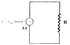
∴ V = IR = Vm sin ωt ⇒ I = \(\frac{\mathrm{V}_{\mathrm{m}}}{\mathrm{R}}\)sin ωt.
∴ Instantaneous current, I = I0 sin ωt. ………….. (2) (∵ I0 = \(\frac{\mathrm{V}_{\mathrm{m}}}{\mathrm{R}}\))
Comparing (1) and (2),
Phase difference between current and voltage is zero.
Phase diagram for purely resistive circuit is as shown figure.
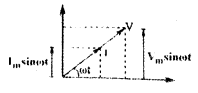
Phase difference between current and voltage is zero.
2) AC through pure Inductor :
Consider a pure inductor with self inductance L connected to an AC of voltage v = vm sin ωt …….. (1)
Let I be the instantaneous current at any time t passing through the inductor.
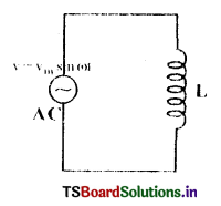
Applying the Krichhoffs law on the circuit, we have
v – L \(\frac{d I}{d t}\) = 0 ……….. (1)
⇒ L\(\frac{d I}{d t}\) = v ⇒ \(\frac{d I}{d t}\) = \(\frac{\mathrm{v}}{\mathrm{~L}}\) = \(\frac{v_m \sin \omega t}{L}\) [∵ v = vm sin ωt]
Integrating it with respect to time, we get
\(\int \frac{d I}{d t}\) dt = \(\frac{\mathrm{v}_{\mathrm{m}}}{\mathrm{L}}\)∫sin (ωt)dt ⇒ I = \(\frac{v_m}{L}\left(\frac{-\cos (\omega t)}{\omega}\right)\) (∵ ∫sin kx = \(\frac{-\cos \mathrm{kx}}{\mathrm{k}}\))
⇒ I = \(\frac{\mathrm{v}_{\mathrm{m}}}{\omega \mathrm{~L}}\) sin(ωt – \(\frac{\pi}{2}\)) …………. (2) [∵ -cos(ωt) = sin(ωt – \(\frac{\pi}{2}\))]
We know amplitude of current Im = \(\frac{\mathrm{v}_{\mathrm{m}}}{\omega \mathrm{~L}}\)
∴ (2) ⇒ I = Im sin(ωt – \(\frac{\pi}{2}\))
Current in an AC inductor circuit is I = Im sin(ωt – \(\frac{\pi}{2}\))
Comparing this with v = vm sinωt, we claim that the current lags the voltage by π/2. The phase difference between the emf and current is π/2 radians and current lags behind the emf by π/2 radians
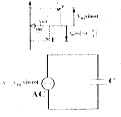
3) AC through pure Capacitor:
Consider a pure capacitor C connected to an AC voltage v = vm sinωt ………. (1)
Let I be the instantaneous current at any time t passing through the capacitor.
The potential difference across the capacitor of capacitance C is v = \(\frac{\mathrm{q}}{\mathrm{C}}\) ………….. (2)
From (1) & (2), \(\frac{\mathrm{q}}{\mathrm{C}}\) = vm sinωt (∵ v = vm sinωt) ⇒ q = C vm sinωt
We know I = \(\frac{d q}{d t}\) ⇒ I = \(\frac{d}{d t}\)(C vm sinωt) ⇒ I = ω C vm cosωt (∵ \(\frac{d}{d x}\) sin kx = k cos kx)
I = ω C vm sin(ωt + \(\frac{\pi}{2}\)) ………… (2) [∵ cos(ωt) = sin(ωt + \(\frac{\pi}{2}\)) ]
We know amplitude of current Im = \(\frac{\mathrm{v}_{\mathrm{m}}}{\omega \mathrm{~L}}=\frac{\mathrm{v}_{\mathrm{m}}}{1 / \omega \mathrm{C}}\) = vmωC
Current in an AC capacitor circuit is I = Im sin (ωt + \(\frac{\pi}{2}\))
Comparing this with v = vm sin ωt, we claim that the current leads the voltage by π/2.
The phase difference between the current and emf is π/2 radians and current through capacitor is ahead of the applied emf by π/2 radians,
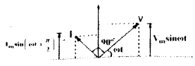
Significance: Phase relationships help to define reactance (XL and XC) and total impedance Z. If power factor cos Φ = 1 the maximum power is dissipated in the circuit.
If power factor cos Φ = 0 then no power is consumed. This leads to the concept of wattless current dissipated even though current is flowing in the circuit
Exercise Problems
Question 1.
The instantaneous emf of an A.C. source is given by ε = 300 sin 314t, what is the rms value of the emf.
Solution:
Given instantaneous emf ε = 300 sin 314t. Comparing this with ε = E0 sinωt we get peak emf E0 = 300V
RMS value of emf is Erms = \(\frac{E_0}{\sqrt{2}}=\frac{300}{\sqrt{2}}=\frac{300}{1.414}\) = 212.13V
Question 2.
A Capacitor has a capacitance of \(\frac{1}{\pi}\)μF. Find its reactance for a frequency of 50 Hz.
Solution:
Given Frequency t = 50Hz , Capacitance C = 1 × 10⁻⁶F
Reactance XC = \(\frac{1}{\omega C}=\frac{1}{2 \pi f C}=\frac{1}{2 \pi \times 50 \times \frac{1}{\pi} \times 10^{-6}}=\frac{1}{100 \times 10^{-6}}=\frac{1}{10^{-4}}\) = 10 kΩ
Question 3.
An Inductor 200 mH, capacitor 500 μF. resistor 100 Ω arc connected in series with a 100 V, AC source. Calculate the current amplitude at resonance and resonance frequency.
Solution:
Given Inductance L = 200mH = 0.2H, Capacitance C = 500 μF= 500 × 10-6 F
Resistance R = 100Ω, RMS voltage VRMS = 100V
(i) Current amplitude Im = \(\frac{V_m}{R}=\frac{\sqrt{2} V_m}{R}=\frac{1.414 \times 100}{100}\) = 1.414 A
(ii) Resonance frequency f = \(\frac{1}{2 \pi \sqrt{L C}}=\frac{1}{2 \times 3.14 \sqrt{0.2 \times 500 \times 10^{-6}}}=\frac{100}{6.28}\) = 15.915 Hz
Question 4.
Determine the impedance of a series LCR circuit, if the reactance of ‘C and ‘L’ arc 250 Ω and 220 Ω. respectively and R is 40 Ω.
Solution:
Given Resistance R = 40Ω, Inductive reactance XL = 250Ω, Capacitive reactance XC = 220 Ω
Impedance Z = \(\sqrt{R^2+\left(X_L-X_C\right)^2}\) = \(\sqrt{40^2+(250-220)^2}\)
= \(\sqrt{1600+900}\) = \(\sqrt{2500}\) = 50Ω
Question 5.
An LCR series circuit with L = 100 mH, C = 100 μF, R = 120 Ω is connected to an A.C, source of emf ε = 30 sin (100 t) volt. Find the impedance. Peak current.
Solution:
Given Inductance L = 100 mH = 100 × 10-3 H, Capacitance = 100 μF = 100 × 10-6 F
Resistance R = 120Ω, emf E = 30 sin 100t ⇒ E0 = 30V, ω = 100 rad/s
Inductance reactance XL = ωL = 100 × 100 × 10-3 = 104 × 10-3 = 10
Capacitive reactance XC = \(\frac{1}{\omega C}=\frac{1}{100 \times 100 \times 10^{-6}}=\frac{1}{10^{-2}}\) = 100Ω
∴ Impedance Z = \(\sqrt{R^2+\left(X_L-X_C\right)^2}=\sqrt{120^2+(10-100)^2}=\sqrt{120^2+90^2}\) = 150Ω
∴ Peak value of current I0 = \(\frac{E_0}{Z}=\frac{30}{150}\) = 0.2A
Question 6.
A Sinusoidal Voltage of Peak Value 283 V and frequency 50 Hz is applied to a series LCR circuit in which R = 3 Ω, L = 25.48 mH and C = 796 μF.
Find (a) the impedance of the circuit (b) the phase difference between the voltage across the source and the current (C) The power dissipated in the circuit.
Solution:
Given f = 50 Hz
∴ Angular frequency ω = 2πf = 2π × 50= 314.16 rad/sec
Inductive reactance XL = ωL = 314.16 × 25.48 × 10-3 = 8Ω [∵ L = 25.48mH]
Capacitive reactance CC = \(\frac{1}{\omega C}=\frac{1}{314.16\left[396 \times 10^{-6}\right]}\) = 4Ω [∵ C = 796 μF]
(a) Impedance Z = \(\sqrt{R^2+\left(X_L-X_C\right)^2}=\sqrt{3^2+[8-4]^2}=\sqrt{9+16}\) = 5Ω
(b) tan Φ = \(\frac{X_L-X_C}{R}=\frac{8-4}{3}=\frac{4}{3}\) ⇒ tan Φ = \(\frac{4}{3}\) ⇒ Φ = tan-1\(\left(\frac{4}{3}\right)\)
∴ The phase difference Φ = Tan-1\(\left(\frac{4}{3}\right)\) = Tan-1(1.33) = 53.1°
RMS voltage Vrms = \(\frac{\mathrm{V}_0}{\sqrt{2}}=\frac{283}{1.414}\) = 200V [∵ V0 = 283V]
RMS Current Irms = \(\)\(\) = 40A [∵ Z = 5 from (1)]
∴ Power dissipated P = Irms2 R = (40)2 × 3 = 1600 × 3 = 4800ω
Question 7.
A coil of inductive reactance 31 Ω has a resistance of 8 Ω. It is placed in series with a condenser of capacitive reactance 25 Ω. The combination is connected to an AC source 110 V. Calculate the power factor of the circuit [Given Cos (36.86) = 0.80, Tan(36.86) = 0.75]
Solution:
Given Inductive reactance XL = 31Ω, Resistance R = 8Ω, Capacitive reactance XC = 25Ω, Voltage V = 110V,
Impedance Z = \(\sqrt{R^2+\left(X_L-X_C\right)^2}=\sqrt{8^2+(31-25)^2}=\sqrt{8^2+6^2}\) = 10Ω
Current I = \(\frac{V}{Z}=\frac{110}{10}\) = 11A
∴ Power factor \(\frac{R}{Z}=\frac{8}{10}\) = 0.8
Question 8.
A step-up transformer operates on a 230 V line and a load current of 2 A. The ratio of the primary and secondary windings is I : 25. What is the current in the primary?
Solution:
Given Primary voltage VP = 230V, Secondary current IS = 2A, Turns ratio NP : NS = 1:25
Transformer ratio \(\frac{N_P}{N_S}=\frac{I_S}{I_P}\) ⇒ \(\frac{1}{25}=\frac{2}{I_P}\)
∴ Primary current IP = 50A
Question 9.
How much current is drawn by the primary of a transformer which steps down 220 V to 22 V to operate a device with an impedance of 220 Ω.
Solution:
Given Primary voltage VP = 220V, Secondary voltage VS = 22V,
Secondary impedance ZS = 220Ω
Secondary current Is = \(\frac{V_S}{Z_S}=\frac{22}{220}\) = 0.1A
∴ Primary current IP = IS × \(\frac{V_S}{V_P}\) = 0.11\(\left(\frac{22}{220}\right)=\) = 0.01A
Question 10.
In an AC circuit, a condenser, a resistor and a pure inductor are connected in series across an alternator (AC generator). If the voltages across them are 20 V, 35 V, 20 V respectively, find the voltage supplied by the alternator.
Solution:
Given VC = 20 V, VR = 35 V, VL = 20 V, V = ?
Formula: V2 = VR2 + (VL – VC)2 = 352 + (20 – 20)2 = 35 V
Question 11.
The primary of a transformer with primary to secondary turns ratio of 1: 2, is connected to an alternator of voltage 200 V. A current of 4A is flowing through the primary coil. Assuming the transformer has no loss. Find the secondary voltage and current are respectively.
Solution:
Given NP : NS = 1 : 2 ⇒ \(\frac{\mathrm{N}_{\mathrm{s}}}{\mathrm{~N}_{\mathrm{p}}}\) = 2, VP = 200 V, IP = 4 A, VS = ? IS = ?
Formula for Transformer ratio: \(\)
Now \(\frac{V_s}{V_p}=\frac{N_s}{N_p}\) ⇒ \(\frac{V_s}{200}=\frac{2}{1}\) ⇒ VS = 400 V
Also \(\frac{I_p}{I_s}=\frac{N_s}{N_p}\) ⇒ \(\frac{4}{\mathrm{I}_{\mathrm{s}}}=\frac{2}{1}\) ⇒ IS = 2 A
Objective Questions
Question 1.
In an A.C. circuit, Irms and I0 are related as
1) Irms = πI0
2) Irms = \(\sqrt{2}\)I0
3) Irms = I0/π
4) Irms = I0/\(\sqrt{2}\)
Answer:
4) Irms = I0/\(\sqrt{2}\)
Question 2.
A 40 μF’ capacitor is connected to a 200 V, 50 Hz ac supply. The r.m.s value of the current in the circuit is, nearly
1)1.7 A
2) 2.05 A
3) 2.5 A
4) 25.1 A
Answer:
3) 2.5 A
Question 3.
In an ac circuit an alternating voltage 200\(\sqrt{2}\) sin 100t volts is connected to a capacitor of capacity 1 μF. The r.m.s. value of the current in the circuit is 1
1) 10mA
2) 100mA
3) 200 mA
4) 20 mA
Answer:
4) 20 mA
Question 4.
A capacitor of capacity C has reactance X. If capacitance and frequency become double then reactance will be
1) 4X
2) X/2
3) X/4
4) 2X
Answer:
3) X/4
Question 5.
An ac. voltage is applied to a resistance R and an inductor L in series. If R and the inductive reactance are both equal to 3Ω, the phase difference between the applied voltage and the current in the circuit is
1) π/6
2) π/4
3) π/2
4) zero
Answer:
2) π/4
Question 6.
A coil has resistance 30 ohm and inductive reactance 20 ohm at 50 Hz frequency. If an ac source, of 200 volt, 100 Hz, is connected across the coil, the current in the coil will be
1) 2.0 A
2) 4.0 A
3) 8.0 A
4) \(\frac{20}{\sqrt{13}}\)A
Answer:
2) 4.0 A
Question 7.
What is the value of inductance L for which the current is maximum in a series LCR circuit with C = 10 μF and ω = 1000 s-1?
1) 1 mH
2) cannot be calculated unless R is known
3) 10 mH
4) 100 mH
Answer:
4) 100 mH
Question 8.
In a circuit L, C and R are connected in series with an alternating voltage source of frequency f. The current leads the voltage by 45°. The value of C is
1) \(\frac{1}{\pi f(2 \pi f L-R)}\)
2) \(\frac{1}{2 \pi f(2 \pi f L-R)}\)
3) \(\frac{1}{\pi f(2 \pi f L+R)}\)
4) \(\frac{1}{2 \pi f(2 \pi f L+R)}\)
Answer:
4) \(\frac{1}{2 \pi f(2 \pi f L+R)}\)
Question 9.
The value of quality factor is
1) \(\frac{\omega L}{R}\)
2) \(\frac{1}{\omega R C}\)
3) \(\sqrt{\mathrm{LC}}\)
4) L/R
Answer:
1) \(\frac{\omega L}{R}\)
Question 10.
An inductor 20 mH, a capacitor 100 pF and a resistor 50 Ω are connected in series across a source of emf, V = 10 sin 314t. The power loss in the circuit is
1) 0.79 W
2) 0.43 W
3) 2.74 W
4) 1.13 W
Answer:
1) 0.79 W
Question 11.
An inductor 20 mH, a capacitor 50 μF and a resistor 40 Ω are connected in series across a source of emf V = 10 sin 340t. The power loss in A.C. circuit is
1) 0.76 W
2) 0.89 W
3) 0.51 W
4) 0.67 W
Answer:
3) 0.51 W
Question 12.
The instantaneous values of alternating current and voltages in a circuit are given as i = \(\frac{1}{\sqrt{2}}\) sin(100πt)ampere e = \(\frac{1}{\sqrt{2}}\) sin(100 πt + \(\frac{\pi}{3}\)) volt
The average power in watts consumed in the circuit is
1) 1/4
2) \(\sqrt{3}\)/4
3) 1/2
4) 1/8
Answer:
4) 1/8
Question 13.
In an a.c. circuit the e.m.f. (e) and the current (i) at any instant are given respectively by
e = E0 sin ωt, i = I0 sin (ωt – Φ)
The average power in the circuit over one cycle of a.c. is
1) \(\frac{E_0 I_0}{2}\)cosΦ
2) E0I0
3) \(\frac{E_0 I_0}{2}\)
4) \(\frac{E_0 I_0}{2}\)sin Φ
Answer:
1) \(\frac{E_0 I_0}{2}\)cosΦ
Question 14.
In an a.c. circuit with phase voltage V and current I, the power dissipated is
1) V.I
2) depends on phase angle between V and I
3) 1/2 × V.I
4) \(\frac{1}{\sqrt{2}}\) × V . I
Answer:
2) depends on phase angle between V and I
Question 15.
In an A.C. circuit, the current flowing is I = 5 sin (100t – π/2) ampere and the potential difference is V = 200 sin (100t) volts. The power consumption is equal to
1) 20 W
2) 0 W
3) 1000 W
4) 40 W
Answer:
2) 0 W
Question 16.
A transistor-oscillator using a resonant circuit with an inductor L (of negligible resistance) and a capacitor C in series produces oscillations of frequency f. If L is doubled and C is changed to 4C, the frequency will be
1) f/2
2) f/4
3) 8f
4) f/2\({\sqrt{2}}\)
Answer:
4) f/2\({\sqrt{2}}\)
Question 17.
A step down transformer connected to an ac mains supply of 220 V is made to operate at 11 V, 44 W lamp. Ignoring power losses in the transformer, what is the current in the primary circuit?
1)4 A
2) 0.2 A
3) 0.4 A
4) 2 A
Answer:
2) 0.2 A
Question 18.
A transformer is used to light a 100 W and 110 V lamp from a 220V mains. If the main current is 0.5 amp, the efficiency of the transformer is approximately
1) 50%
2) 90%
3) 10%
4) 30%
Answer:
2) 90%
Question 19.
The core of a transformer is laminated because
1) ratio of voltage in primary and secondary may be increased
2) energy losses due to eddy currents may be minimised
3) the weight of the transformer may be reduced
4) rusting of the core may be prevented.
Answer:
2) energy losses due to eddy currents may be minimised
Question 20.
A step-up transformer operates on a 230 V line and supplies a load of 2 ampere. The ratio of the primary and secondary windings is 1 : 25. The current in the primary is
1) 15 A
2) 50 A
3) 25 A
4) 12.5 A
Answer:
2) 50 A
Question 21.
The primary winding of a transformer has 500 turns whereas its secondary has 5000 turns. The primary is connected to an A.C. supply of 20 V, 50 II/. The secondary will have an output of
1) 2 V, 50 Hz
2) 2 V, 5 Hz
3) 200 V, 50 Hz
4) 200 V, 500 Hz.
Answer:
3) 200 V, 50 Hz
Question 22.
A coil of 40 henry inductance is connected in series with a resistance of 8 ohm and the combination is joined to the terminals of a 2 volt battery. The time constant of the circuit is
1) 5 seconds
2) 1/5 seconds
3) 40 seconds
4) 20 seconds
Answer:
1) 5 seconds
Question 23.
The time constant of C-R circuit is
1) 1/CR
2) CIR
3) CR
4) R/C
Answer:
3) CR