Telangana SCERT 10th Class Physics Study Material Telangana 9th Lesson Electric Current Textbook Questions and Answers.
TS 10th Class Physical Science 9th Lesson Questions and Answers Electric Current
Improve Your Learning
I. Reflections on concepts
Question 1.
Explain how electron flow causes electric current with Lorentz-Orude’s theory of electrons.
Answer:
1. Lorenti and Drude, scientists of 19th Century proposed that conductors like metals contain large number of free electrons while the positive ions are fixed in their locations. The arrangement of the positive ions is aimed lattice.
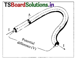
2. Assume that a conductor is an open circuit. The electrons move randomly in lattice space of a conductor as shown in the following figure.
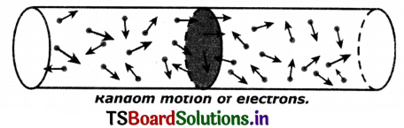
3. When the electrons are in random motion, they can move in any direction.
4. Hence if we imagine any cross-section as In above figure, the number of electrons, crossing the cross-section of a conductor from left to right in one second is equal to that of electrons passing the cross-section from right to left in one second and the nett charge moving along conductor through any cross-section Is zero when the conductor is in open circuit.
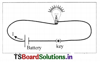
5. When the ends of the conductor are connected to a source (say, battery) through a bulb, the bulb glows because energy transfer takes place from battery to the bulb.
6. As the electrons are responsible for transfer of energy from battery to the bulb, they must have an ordered motion.
7. When the electrons are in ordered motion there will be a net charge crossing any cross-section of the conductor.
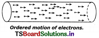
8. This ordered motion of electrons Is called electric current.
Question 2.
Write the difference between potential difference and emf.
Answer:
| Potential difference (pd) | Electro motive force (emf) |
| 1. Work done by the electric force on unit positive charge to move it through a distance ‘l’ from A to B is called potential difference between those points. | 1. emf is defined as work done by the chemical force to move unit positive charge from negative terminal to positive terminal of the battery. |
| 2. Potential difference V = \(\frac{W}{q}=\frac{F_e l}{q} \) | 2. emf ε = \(\frac{W}{q}=\frac{F_e d}{q} \) |
| 3. The S.I unit of potential difference is Volt. | 3. The S.I unit of emf is Volt’. |
| 4. Potential difference can be measured by using a voltmeter, which is connected parallel in a circuit. | 4. emf can be measured by using volt meter, which is connected parallel in between two terminals in a circuit. |
Question 3.
How can you verify that the resistance of a conductor is temperature dependent?
Answer:
- Take a bulb and measure the resistance of the bulb using a multimeter in open circuit. Note the value of the resistance.
- Now connect the bulb in a circuit and switch on the circuit.
- After a few minutes the bulb gets heated.
- Now measure the resistance of the bulb again with multimeter.
- The value of resistance of the bulb in second instance is more than the resistance of the bulb in open circuit.
- Here the increase in temperature of the filament in the bulb is responsible for increase in resistance of the bulb.
- Thus the value of resistance of a conductor depends on the temperature.
Question 4.
What do you mean by electric shock? Explain how it takes place.
Answer:
- If we touch live wire of 240V which gives 0.0024 A of current flows through the body the function g of organs inside the body gets disturbed.
- This disturbance inside the body is felt as electric shock.
- If the current flow continues further, it damages the tissues of the body which leads to decrease ¡n resistance of the body.
- When this current flows for a longer time, damage to the tissues increases and there by the resistance of human body decreases further.
- Hence, the current through the human body will increase.
- If this current reaches 0.07 A, it affects the functioning of the heart.
- If this current passes through the heart for more than one-second t could be fatal.
Question 5.
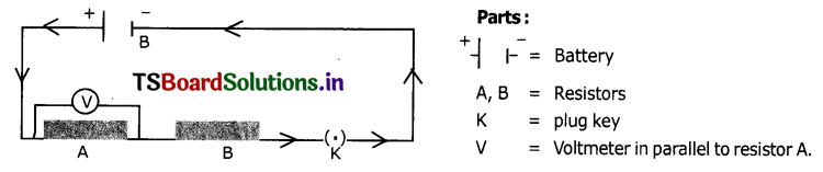
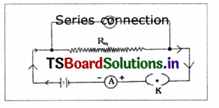
Draw a circuit diagram for a circuit in which two resistors A and B are connected in series with a battery and a voltmeter is connected to measure the potential difference across the resistor A.
Answer:
A circuit diagram in which two resistors A and B are connected ¡n series with a battery and a voltmeter is connected to measure the p.d. across the resistor A.
Question 6.
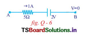
In the below figure, the potential at A is ……………………… when the potential at B is zero.
Answer:
Apply Kirchoff’s loop rule VA-5 x 1 – 2—Vb=0
VA-5 – 2-0 =0 ⇒VA = 7V
The potential at A = 7V when the potential at B = O
Question 7.
How does a battery work? Explain.
Answer:
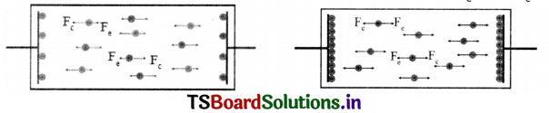
1. A battery consists of two metal plates (electrodes) and a chemical (electrolyte).
2. This electrolyte consists positive and negative ions which move In opposite directions.
3. This electrolyte exerts a force called chemical force (Fc) to make the ions move in a specified direction.
4. Positive Ions move towards one plate and accumulate on that. As a result this plate becomes positively charged (Anode).

5. Negative Ions move to another plate and accumulate on that. As a result of this the plate becomes negatively charged (Cathode).
6. This accumulation continues till both plates are sufficiently charged.
7. But the ions experience another force called electric force (Fe) when sufficient number of charges accumulated on the plates.
8. The direction of Fe is opposite to Fc and magnitude depends on the amount of charge accumulated on the plates.
9. The accumulation of charges on plates is continuous till Fe becomes equal to Fc Now there will not be any motion due to balance of Fe and Fc.
10. The new battery that we buy from the shop is under the Influence of balanced forces. This Is the reason for the constant RD. between the terminals of a battery.

11. When a conducting wire Is connected to the terminals of the battery, a RD. is created between the ends of the conductor which sets up an electric field through-out the conductor.
12. The large number of electrons In the conductor, near the positive terminal of the battery are attracted by It and start to move towards positive terminal. As a result the amount of positive charge on this plate decreases. So Fe becomes weaker than Fc and Fc pulls negative ions from anode towards cathode.
13. The negative terminal pushes one electron into the conductor because of stronger repulsion between negative terminal and negative ion.
14. Hence. the total number of electrons in the conductor remains constant during the current flow. The above-said process continues till Fe = Fc.
Question 8.
Explain Kirchhoff’s laws with examples.
Answer:
Kirchhoffs laws:
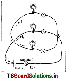
1. The junction law: At any junction point in a circuit where the current can divide, the sum of the currents in the junction must equal to the sum of the currents leaving the junction.
This means that there is no accumulation of electric charges at any junction in a circuit. Eg: ‘P Is the junction
I1, I4, and I6 are the currents into the junction.
I2, I3, and I5 are the currents leaving the junction.
According to Kirchhoff’s junction law
I1+I4+I6 = I2+I3+I5

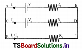
2) The loop law: The algebraic sum of the increases and decreases in potential difference across various components of a closed circuit loop must be zero.
Eg: For the loop ACDBA
-V2+I2R2-I1R1 +V1=O
For the loop EFDCE
– (I1 + I2) R3 -I2R2 + V2 = O
For the loop EFBAE
-(I1+I2)R3-I1R1+V1=O
Question 9.
Deduce the expression for the equivalent resistance of three resistors connected In series.
Answer:
Two or more resistors are said to be connected in series if the current flowing through one, also flows through the others.
In series combination, we know that
1. The same current passes through the resistors.
2. The potential difference across combination of resistors is equal to the sum of the voltages across the individual resistors.
Connect the circuit as shown n the figure.
The cell connected across the series combination of 3 resistors maintains a potential difference (v) across the combination. The current through the combination is I.
Let us replace the combination of 3 resIstors by a single resistor Req such that current does not change.
Req is given by Ohm’s law as
Req = \( \frac{V}{I}\)
⇒V=IReq
The potential differences V1, V2, V3 across the resistors R1, R2 and R3
respectively are given by Ohm’s law as
V1 = IR1, V2 = IR2, V = IR3
Since the resistances are connected in series
V= V1 +V2+V3
IReq = IR1 + IR2 + IR3
I (Req) = I (R1 + R2 + R3)
⇒ Req = R1 + R2 + R3
Similarly, for n resistors connected in series,
Req = R1 + R2 + R3+ ………………………. +Rn.
Question 10.
Deduce the expression for the equivalent resistance of three resIstors connected In parallel.
Answer:
If resistances are connected in such a way that the same potential difference gets applied across each of them, they are said to be connected In parallel.
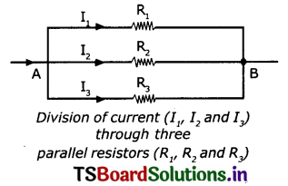
For a parallel combination, we know that,
- The total current flowing Into the combination is equal to the sum of the currents passing through the individual resistors ⇒ I = I1+ I2+ I3
- The potential difference remains constant V1 = V2 = V3 = V.
Connect the circuit as shown in the figure. - The cell connected across 3 resistors maintains the same potential difference across each resistor.
- The current I gets divided at A into 3 parts I1 I2 and I3 which flows through R1, R2, and R3 respectively.
- Let us replace the combination of resistors by an equivalent resistance Req such that potential difference across the circuit does not change.
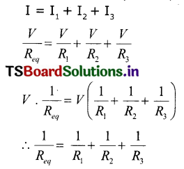
- The equivalent resistance Req = \(\frac{V}{I} \Rightarrow I=\frac{V}{R_{e q}}\)
- The currents I1,I2,I3 across R1,R2 and R3 are given by I1 = \(\frac{V}{R_1}\), I2 = \(\frac{V}{R_2} \), I3 = \(\frac{V}{R_3} \),
Since the resistors are in parallel,
Question 11.
What is the value of 1KWH in joules?
Answer:
1 KWH = (1000 J/s) (60 × 60s) = 3600 × 1000J = 3.6 × 10⁶ So, 1KWH is equal to 3.6 x 10⁶ Joules.
Question 12.
Silver is a better conductor of electricity than copper. Why do we use copper wire for conduction of electricity?
Answer:
Reasons:
- Copper has low resistivity. When electricity is passed through copper wires, the power losses in the form of heat are very small.
- Cost of copper versus that of silver metal, copper is less expensive.
- Copper has flexibility and resistance to breakage.
- Copper is cheaply available than silver.
Application of concepts
Question 1.
Explain overloading of household circuit.
Answer:
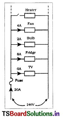
- Electricity enters our homes through two wires called lines. These lines have low resistance and the potential difference between the wires is usually about 240 V.
- All electrical devices are connected in parallel in our home. Hence, the potential drop across each device is 240 V.
- Based on the resistance of each electric device, it draws some current from the supply. Total current drawn from the mains is equal to the sum of the currents passing through each device.
- If we add more devices to the household circuit the current drawn from the mains also increases.
- This leads to overheating and may cause a fire. This is called “overloading”.
For example:
If we switch on devices, such as heater shown in the figure, from the mains exceeds the maximum limit 20 A.
Question 2.
Why do we use fuses in household circuits?
Answer:
- The fuse consists of a thin wire of low melting point.
- To prevent damages due to overloading we connect an electric fuse to the household circuit.
- When the current in the fuse exceeds 20A, the wire will heat up and melt.
- The circuit then becomes open and prevents the flow of current into the household circuit. So all the electric devices are saved from damage that could be caused by overload.
- Thus, we can save the household wiring and devices by using fuses.
Question 3.
Two bulbs have ratings 100W, 220V, and 60W, 220V. Which one has the greater resistance?
Answer:
Resistance of first bulb R1 = \(\frac{V^2}{P}=\frac{220 \times 220}{100}\) = 484 Ω
Resistance of second bulb R2 = \(\frac{V^2}{P}=\frac{220 \times 220}{60}=\frac{4840}{6}\) = 806.6Ω
∴ The bulb rated 60W, 220V has higher resistance.
Question 4.
Why don’t we use series arrangement of electrical appliances like bulb, Television, fan and others in domestic circuits?
Answer:
- We have seen that in a series circuit, the current is constant throughout the electric circuit.
- But it is obviously impracticable to connect an electric bulb and an electric heater in series because they need currents of widely different values to operate properly.
- Another major disadvantage of a series circuit is that when one component fails, the circuit is broken and none of the other components works.
Question 5.
Are the headlights of a car connected in series or parallel? Why?
Answer:
The headlights of a car are connected in parallel.
Reason:
- When they are connected in parallel, same voltage (P.D) will be maintained in the two lights.
- If one of the lights damaged, the other will work without any disturbance.
Question 6.
Why should we connect electric appliances in parallel in a household circuit? What happens if they are connected in series?
Answer:
We should connect the electric appliances in parallel to household circuit because
- Each appliance gets the full voltage.
- The parallel circuit divide the current through the appliances. Each appliance gets proper current depending on its resistance.
- If one appliance is switched on/off others are not affected.
If appliances are connected in series the following disadvantages are arised:
- The same current will flow through all the appliances, which is not desired.
- Total resistance becomes large and the current gets reduced.
- We cannot use independently on/off switches with individual appliances.
- All appliances have to be used simultaneously even if we don’t need them.
Question 7.
If the resistance of your body is 10000012, what would be the current that flows in your body when you touch the terminals of a 12V battery?
Answer:
Resistance of the body (R) 1,00,000 Ω
Potential difference of the battery (V) =12V
Current that flows in the body (I) = ?
According to Ohm’s law, \(\frac{V}{I}\) = R
⇒ I = \(\frac{V}{R}=\frac{12}{1,00,000}\) = 0.00012 A
Question 8.
A wire of length 1m and radius 0.1 mm has a resistance of 100W. Find the resistivity of the material.
Answer:
Resistance of wire, R = 100 Ω
Radius of wire, r = 0.1mm = 1 x 10⁻⁴ m
Length of wire, l = 1m
Formula for resistivity of wire: ρ = \(\frac{R A}{l}=\frac{R \pi r^2}{l} \)
Substituting the given values, ρ = \(\frac{22}{7} \times 10^2 \times \frac{10^{-4} \times 10^{-4}}{l} \) = \(\frac{22}{7} \times 10^{-6} \) ohm—meter
= 3.14 × 10⁻⁶ ohm-mt
Question 9.
Why do we consider tungsten as a suitable material for making the filament of a bulb?
(Or)
What is the reason for using tungsten as a filament in electric bulb?
Answer:
Tungsten has a high resistivity value (5.60 ×10⁻⁸ m) and a high melting point (3422°C). So the filament of a bulb is usually made of tungsten. Its high resistivity enables the filament to become red hot soon and then it produces white heat to emit light. Its high melting point keeps it in a solid state and also prevents oxidation.
Question 10.
How can you appreciate the role of a small fuse in house wiring circuit in preventing damage to various electrical appliances connected to the circuit?
Answer:
- The fuse consists of a thin wire of low melting point. When the current in the fuse exceeds $20 \mathrm{~A}$, the wire will heat up and melt.
- The circuit then becomes open and prevents the flow of current into the household circuit. So all the electric devices are saved from change that could be caused by overload.
- Thus we can save the house holding wiring and devices by using fuses.
- So we should appreciate the role of fuse in preventing damage to electrical appliances in household circuits.
Question 11.
Uniform wires of resistance 100c are melted and recast into wire of length double that of the original. What would be the resistance of the new wire formed?
Answer:
Before recasting,
Resistance R1 = 100 Ω
length (l1)= l (say)
After recasting
Resistance R2 = ?
length (‘l2) = 2l
We know that R α l,
\(\frac{R_1}{R_2}=\frac{l_1}{l_2}\)

Higher Order Thinking Questions
Question 1.
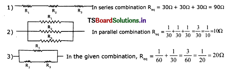
Imagine that you have three resistors of 30 Ω each. How many resultant resistances can be obtained by connecting these three in different ways. Draw the relevant diagrams.
Answer:
Let R1 = 30Ω, R2 = 30Ω, R3 = 30Ω
We get different resistors by different combinations as shown below.
Question 2.
A house has 3 tube lights, two fans and a Television. Each tube light draws 40W. The fan draws 80W and the Television draws 60W. On the average, all the tube lights are kept on for five hours, two fans for 12 hours and the television for five hours every day. Find the cost of electric energy used in 30 days at the r ate of Rs. 3.00 per Kwh.
Answer:
Power consumption by tube lights in a day = 40W x 3 x 5H = 600 WH
Power consumption by fans in a day = 80W x 2 x 12H = 1920 WH
Power consumption by television in a day = 60W x 1 x 5H = 300 WH
Total power consumption in a day = 600 + 1920 + 300 = 2820 WH
Power consumption for 30 days = 2820 x 30 = 84600 WH

Rate of 1 KWH = Rs 3/- Total consumption = 84.60 x Rs.3 = Rs. 253.80
Question 3.
Observe the circuit and answer the questions given below:
(i) Are resIstors 3 and 4 In series?
(ii) Is the battery in series with any resistor?
(iii) What is the potential drop across the resistor 3?
(iv) What is the total emf in the circuit if the potential drop across resistor 1 is 6V?
Answer:
(i) No. Resistors 3 and 4 are not in series. They are in parallel.
(ii) No.
(iii) As resistors 3 and 4 are in parallel, same potential difference will be allowed
through them. Hence the potential drop across resistor 3 is 8V.
(iv) Total emf=V1+V2+V3+V4=6V+14V+8V+8V=36V.
Multiple choice questions
Question 1.
A uniform wire of resistance 50 Q is cut into five equal parts. These parts are now connected in parallel. Then the equivalent resistance of the combination is : ( )
(A) 2 Q
(B) 12 Q
(C) 250 Q
(D) 6250 Q
Answer:
(A) 2 Q
Question 2.
A charge is moved from a point A to a point B. The work done to move unit charge during this process is called ( )
(A) potential at A
(B) potential at B
(C) potential difference between A&B
(D) current from A to B
Answer:
(C) potential difference between A&B
Question 3.
Joule / coulomb is the same as ( )
(A) 1-watt
(B) 1-volt
(C) 1 ampere
(D) 1-ohm
Answer:
(B) 1-volt
Question 4.
The resistors of values 2 Ω, 4 Ω, and 6 Ω are connected in series. The equivalent resistance in the circuit is ( )
(A) 2 Ω
(B) 4 Ω
(C) 12 Ω
(D) 6 Ω
Answer:
(C) 12 Ω
Question 5.
The resistors of values 3 Ω, 6 Ω, and 18 Ω are connected in parallel. The equivalent resistance in the circuit is ( )
(A) 12 Ω
(B) 36 Ω
(C) 18 Ω
(D) 1.8 Ω
Answer:
(D) 1.8 Ω
Question 6.
The resistors of values 6 Ω, and 6 Ω are connected in series and 12 Ω are connected in parallel. The equivalent resistance of the circuit is ( )
(A) 24 Ω
(B) 6 Ω
(C) 18 Ω
(D) 2.4 Ω
Answer:
(B) 6 Ω
Question 7.
The current in the wire depends ( )
(A) only on the potential difference applied
(B) only on the resistance of the wire
(C) on both of them
(D) none of them
Answer:
(C) on both of them
Suggested Experiments
Question 1.
State Ohm’s law. Suggest an experiment to verify it and explain the procedure.
Answer:
A. Ohm’s Law: The potenbal difference between the ends of a conductor is directly proportional toe the electric current passing through it at constant temperature.
Verification:
Aim: To verify Ohm’s law or to show that -=Co,,ctani
Materials required: 5 dry cells of 1.5V each, conducting wires, an ammeter,
a voltmeter, Manganin wire of length 10cm, LED and Key.

Procedure:
1. Connect a circuit as shown in figure.
2. Solder the connecting wires to the ends of the Manganin wire.
3. Close the key.
4. Note the readings of current from Baltery Key ammeter and potential difference from volt meter in the following table.
| Potential difference (V) | Current (I) | V/I |
5. Now connect 2 cells (in series) instead of one cell in the circuit. Note the values of ammeter and voltmeter and record them in the above table.
6. Repeat the same for three cells, four cells, five cells respectively.
7. Record the values of V and I corresponding to each case in the table.
8. Find \(\frac{V}{I} \) for each set of values.
9. We notice that \(\frac{V}{I} \) is a constant.
V ∝ I ⇒ \(\frac{V}{I} \)= Constant
This constant is known as resistance of the conductor, denoted by R.
⇒ \(\frac{V}{I} \) = R
∴ Ohm’s law is verified.
Question 2.
How do you verify that resistance of a conductor is proportional to the length of the conductor for constant cross-section area and temperature?
Answer:
1. Collect Iron spokes of different lengths with the same cross-sectional area.
2. Make a circuit as shown in the figure.
3. Connect one of the iron spokes between P and Q.
4. Measure the value of the current using the ammeter connected to the circuit and note in your notebook.
5. Repeat this for other lengths of the iron spokes. Note the corresponding values of currents in your notebook as shown below.
| Length Of Iron Spoke | Current (i) |
- We observe that current decreases as the length of the spoke increases.
- We also know that resistance increases as current decreases.
- Hence the resistance of iron spoke increases as its length increases.
- We conclude that the resistance of a conductor is directly proportional to its length for a constant-potential difference and constant cross-sectional area.
R ∝ l
Suggested Projects
Question 1.
a. Take a battery and measure the potential difference. Make a circuit and measure the potential difference when the battery is connected in the circuit. Is there any difference in potential difference of battery?
Answer:
- The potential difference across the terminals of a battery when it is not connected in any circuit is called the Electromotive force of battery or emf of battery.
- As soon as the battery is connected to an external circuit, there will be a current through the battery as well as the external circuit.
- Due to this current flowing through the battery, there will be a voltage drop inside the battery because of the internal resistance of the battery itself.
- Hence when external circuit is connected, the voltage appeared across the terminal of the battery is somewhat less than the open circuit voltage of the battery.
- This is because of voltage drop due to internal resistance ¡nside the battery.
b. Measure the resistance of a bulb (filament) in open circuit with a multimeter. Make a circuit with elements such as bulb, battery of 12V and key in series. Close the key. Then again measure the resistance of the same bulb (filament) for every 30 seconds. Record the Observations in a proper table. What can you conclude from the above results?
Answer:
Materials required: a bulb, 12 v battery, key, and multimeter.
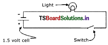
Procedure:
- Measuretheresistanceofabulb in open circuit.
- Connect the bulb, battery and a key in series in a circuit as shown in fig.
- Close the key and measure the resistance of a bulb for every 30 seconds with a multimeter and note down them in the following table.
Observations: Resistance of the bulb in open circuit = 4.3 Q.
| Time (n sec) | Resistance of the bulb (filament) in (Ohms) |
| 0 | 4.3 |
| 30 | 4.6 |
| 60 | 4.9 |
| 90 | 5.1 |
| 120 | 5.4 |
| 150 | 5.6 |
| 180 | 5.9 |
Conclusion:
- From the above observations, it is clear that the resistance of a bulb (filament increases as the time increases.
- This Is because, as the current passes through the filament of a bulb, filament gets heated up and its temperature increases.
- As the temperature of the filament increases, its 20 resistance also increases
- So, the resistance of a conductor depends upon its temperature.
Question 2.
Calculate the resistance of venous bulbs that you use at your home and find which one is having higher / lower resistance value. Write the report on your observations.
Answer:
We are using following types of bulbs in my bouse,
- In candescent bulb (100 W)
- Fluorescent tube lights (40 W)
- CFL lamp (20 W)
- LED bulb (10 W)

Conclusion:
- From the above observations, it is clear that the LED bulb of low wattage has higher resistance.
- So, it is clear that the resistance of a electrical appliance is more ¡f its wattage is less.
Question 3.
Collect the information and prepare a report on power consumption in your home/school.
Answer:
In my house, we are using the following electric appliances.
Tubelights (40 W) – 3 (Using daily each for 8 hours)
Fans(80 W) – 3 (UsIng daily each for 10 hours)
Television (60 W) – 1 (UsIng daily each for S hours)
Electric heater (1000 W) – 1 (Using daily each for 30 mm)
Calculation of power consumption :
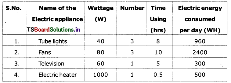
Total electric energy consumed Per Day = 4160 WH
Conclusion:
Total electric energy consumed for one month (30 days) = 4160 x 30 = 1248000
Total electric energy consumed for one month in KWH = \(\frac{124800}{1000} \) = 124.8 KWH
∴ We are consuming nearly 125 KWH (units) of electric energy in my house in a month.
TS 10th Class Physical Science Electric Current Intext Questions
Page 176
Question 1.
What do you mean by electric current?
Answer:
The flow of electrons in a particular direction is called electric current.
Question 2.
Which type of charge (+ve or -ve) flows through an electric wire when it is connected in an electric circuit?
Answer:
Electrons carry nagative charge. So negative charge flows through circuit.
Question 3.
Is there any evidence for the motion of charge in daily life situations?
Answer:
- Lightning, which is observed in the sky at the time of heavy rain is an evidence for the motion of charge in the atmosphere.
- When we put the switch of an electric lamp ‘on’, the bulb glows. It is also evidence to motion of charge.
Question 4.
Does motion of charge always lead to electric current?
Answer:
Yes.
Question 5.
What do you notice in activity 1?
Answer:
The bulb glows.
Page 177
Question 6.
Can you predict the reasons for the bulb not glowing in situations 2 & 3?
Answer:
- In situation 2, the source of current, namely battery is removed from circuit. So the bulb does not glow.
- In situation 3, nylon wires do not conduct electricity. Nylon is a non-conductor. So the bulb does not glow.
Question 7.
Why do all materials not act as conductors?
Answer:
The materials in which electrons do not move freely do not act as conductors.
Question 8.
How does a conductor transfer energy from source to bulb?
Answer:
The electrons in a conductor move randomly in lattice space of conductor. These electrons transfer energy from source to bulb.
Question 9.
What happens to the motion of electrons when the ends of the conductor are connected to the battery?
Answer:
When the ends of the conductor are connected to the battery, the transfer of charged particles takes place from battery to bulb and again to the battery. As the circuit is complete and closed the bulb glows.
Page 178
Question 10.
Why do electrons move in specified direction?
Answer:
When the conductor Is connected to a battery, a uniform electric field is set up throughout the conductor. This field makes the electrons move towards positive end.
Question 11.
In which direction do the electrons move?
Answer:
The free electrons in the conductor are accelerated by the electric field and move in a direction opposite to the direction of the field.
Question 12.
Do the electrons accelerate continuously?
Answer:
No
Question 13.
Do they move with constant speed?
Answer:
The electrons collide with lattice ions, lose energy and may even come to rest at every collision.
Page 179
Question 14.
Why does a bulb glow immediately when we switch on?
Answer:
When we switch on any electric circuit, irrespective of length of the connecting wire, an electric field is set up throughout the conductor instantaneously, due to the potential difference of the source connected to the circuit. This electric field makes all the electrons move in a specified direction simultaneously. So the bulb glows immediately.
Question 15.
How can we decide the direction electric current?
Answer:
The direction of electric current is determined by the signs of the charge (q) and drift speed (y).
Page 180
Question 16.
How can we measure electric current?
Answer:
We can measure electric current, using an Ammeter.
Question 17.
Where do the electrons get energy for their motion from?
Answer:
The field exerts a force on the charge (electrons) The free charges accelerate the electric field, if the free charges ar electrons, then the direction of electric force on them ‘s opposite to the direction of electric field. It means that the electric field does some work to move free charges in a specified direction.
Question 18.
Can you find the work done by the electric force?
Answer:
Work done by the electric force on a free charge q ‘s given by W = EJ.
Page 181
Question 19.
What Is the direction of electric current In terms of potential difference?
Answer:
In terms of potential difference, the direction of electric current is from positive terminal to the negative terminal.
Question 20.
Do positive charges move In a conductor? Can you give an example of this?
Answer:
In electrolytic positive charges move towards of negative electrode.
Question 21.
How dosas battery maintain a constant potential difference between Ita terminals?
Answer:
The accumulation of charge on plates continues till the electric force F becomes equal to chemical force F, At this situation, the potential difference between the terminals Is maintained constant.
Question 22.
Why does the battery discharge when ita positive and negative terminals are connected through s conductor?
Answer:
When a conducting wire is connected to the terminals of the battery, a potential difference Is created between the ends and it sets up an electric field throughout the conductor. The electrons near the positive terminal of the battery are attracted by it and start moving towards positive terminal. As a result, the amount of positive charge on the plate decreases and the F becomes weaker than F. So the battery becomes discharged.
Page 182
Question 23.
What happens when the battery is connected in a circuit?
Answer:
When a conducting wire is connected to the terminals of the battery, a potential difference is created between the ends of the conductor. This potential difference sets up an electric field throughout the conductor and Its direction is from positive terminal to negative terminal In the conductor.
Page 183
Question 24.
How can we measure potential difference or emf?
Answer:
Generally, a voltmeter s used to measure potential difference or emf.
Page 184
Question 25.
Is there any relation between emf of battery and drift speed of electrons in the conductor connected to a battery?
Answer:
The ratio of emf and drift speed of electrons Is constant for some materials at constant temperatures.
Page 186
Question 26.
Can you guess the reason why the ratio of V and I in case of LED Is not constant?
Answer:
LED (Light Emitting Diode) is made up of semiconducting material. It is non Ohmic material and so the ratio of V and I in case of LED is not constant.
Question 27.
Do all materials obey Ohm’s law?
Answer:
No. Some materials such as silicon, germanium etc. do not obey Ohm’s law.
Question 28.
Can we classify the materials based on Ohm’s law?
Answer:
Yes. Based on Ohms’s law materials are classified into three categories.
They are:
- Ohmic materials,
- Non-Ohmic materials and
- Semiconductors.
Question 29.
What is resistance?
Answer:
Resistance of a conductor is the obstruction to the motion of electrons in a conductor.
Question 30.
Is the value of resistance the same for all materials?
Answer:
No. Silver and copper have least resistance value. Other materials such as iron, aluminum etc. have little higher resistance values. Tungsten has a very high resistance value.
Question 31.
Is there any application of Ohm’s law in daily life?
Answer:
Ohm’s law has a wide application in daily life:
- We use materials like copper which are ohmic conductors to make household electrical wiring and in Industries.
- Semiconductors which find an extensive application in modern electronic devices such as TV, DVD, Computers etc., are made up of non-ohmic materials.
- The fuse, a device which protects household electrical appliances from high-voltage electric currents, is also an application of Ohm’s law.
Question 32.
What causes electric shock in the human body-current or voltage?
Answer:
It Is the electric current that causes electric shock in the human body. When 0.0024 Amperes of current flows through human body the functioning of organs inside the body gets disturbed. This disturbance inside the body Is felt as electric shock. ¡f the current flow continues further, It damages the tissues of the body which leads to decrease in resistance of the body.
Page 187
Question 33.
Do you know the voltage of mains that we use in our household circuits?
Answer:
The voltage of mains that we use in our household circuits is 240V. Usually, it varies between 220V and 240V.
Question 34.
What happens to our body if we touch live wire of 240V?
Answer:
The current passing through our body when we touch a live wire of 240V is given by, I= \(\frac{240}{100000}\) = 0.024 A
When this quantity of current flows through the body the functioning of organs inside the body gets disturbed. This disturbance inside the body is felt as electric shock and damages the tissues of the body.
When this current flows for a longer time, damage to tissues increases and resistance of body decreases.
A current of 0.07A, effects the functioning of heart and it may lead to fatal consequences.
Page 188
Question 35.
Why does not a bird get a shock when it stands on a high-voltage wire?
Answer:
- There are two parallel transmission lines on electric poles.
- The p.d. between the two lines is 240 V throughout their lengths.
- When the bird stands on a high-voltage wire, there is no potential difference between the legs of the bird because it stands on a single wire.
- If the two lines are connected across by a conducting device, then only current flows between the wires.
- As the bird stands on a single wire no current passes through its body.
- So, it does not feel any electric shock.
Page 189
Question 36.
What could be the reason for an increase in the resistance of the bulb when current flows through it?
Answer:
- As the bulb glows it gets heated.
- The increase in temperature of the filament in the bulb is responsible for increase in resistance of the bulb since resistance is temperature dependent.
Question 37.
What happens to the resistance of a conductor If we increase its length?
Answer:
The resistance of a conductor increases with the increase in its length.i.e., R α l
Page 190
Question 38.
Does the thickness of a conductor influence its resistance’?
Answer:
Yes. The resistance of a conductor decreases with Increase in Its thickness. i.e., R α\(\frac{1}{A}\) (A = thickness or cross-section area of conductor)
Page 192
Question 39.
How are electric devices connected in circuits?
Answer:
Electric devices are connected in circuits either is series combination or an parallel combination.
Page 193
Question 40.
What do you notice in activity 6?
Answer:
In series connection of resistors, there Is only one path for the flow of current in the circuit. If the current in the entire circuit is I, It Is the same current lin the parts also.
Question 41.
What do you mean by equivalent resistance?
Answer:
If the current drawn by a resistor is equal to the current drawn by the combination of resistors, then the resistor is called as equivalent resistor.
Question 42.
What happens when one of the resistors In series breaks down?
Answer:
When one of the resistors In senes combination breaks down, the circuit becomes open and flow of current cannot take place In the circuit.
Question 43.
Can you guess in what way household wiring has been done?
Answer:
The household wiring has been done in parallel combination because
(i) the equivalent resistance of the parallel combination is less than the resistance of each of the resistors and (ii) through one of the resistors in parallel combination is cut off the other resistors continue to work.
Page 194
Question 44.
How much current is drawn from the battery?
Answer:
Measure the current (1) drawn from the battery using the ammeter and it Is 1.5 amps.
Question 45.
Is it equal to Individual currents drawn by the resistors?
Answer:
Yes, the current drawn from the battery‘s equal to the sum of individual currents drawn by the individual resistors (here bulbs).
That is, I=I1 +I2+I3+ ……………………….. .
Page 199
Question 46.
You might have heard the sentence like “this month we have consumed 100 units of current”. What does unit mean?
Answer:
The electric appliances that we use n our daily life consume electric energy.
This energy Is measured in units.
i.e., 1 unit = 1 K.W,H. (Kilo Watt hour)
⇒ 1 K.W.H = 1000 W.H.
Question 47.
A bulb Is marked “60w and 120V”. What do these values Indicate?
Answer:
60 W and 120 V’ marked on a bulb indicates that If the bulb is connected to 120 volts mains, it will be able to convert 60 Watts of electrical energy into heat or light in one second.
Page 200
Question 48.
What is the energy lost by the charge in 1 Sec?
Answer:
The energy lost by the charge is equal to W/t where W = Work done and ‘t’ is the time in seconds.
Page 201
Question 49.
What do you mean by overload?
Answer:
- Electricity enters our homes, through two wires called lines.
- These line wires have low resistance and the p.d. of the wires is usually 240V.
- These two line wires run throughout the household circuit to which we connect various appliances such as bulbs, fans, TV, refrigerator, air cooler etc.
- These appliances are connected in parallel combination.
- It we add more devices to the household circuit the current drawn from the mains abnormally increases. This is called overload.
Question 50.
Why does It cause damage to electric appliances?
Answer:
- The maximum current that we can draw from the mains is 20A.
- When the current drawn from the mains Is more than 20A, overheating occurs and may cause a fire.
- It also causes damage to electrical appliances.
Question 51.
What happens when this current Increases greatly?
Answer:
When the current drawn from the mains is more than 20A, overheating occurs and may cause breaking of fire. This is called overloading and causes the damage of electrical appliances. Sometimes it may lead to fire accidents
Page 202
Question 52.
How can we prevent damage due to overloading?
Answer:
To prevent damage due to overloading an electric fuse is connected in the household circuit.
Think And discuss
Question 1.
What do you mean by short circuit?
Answer:
Short circuit means a connection across an electric circuit with a very low resistance, by an insulation failure etc. Current passes through this by pass.
Question 2.
Why does a short circuit damage electric wiring and devices connected to it?
Answer:
As the current takes short cut, which results in heating or burning which damages the wiring and devices connected to it.
TS 10th Class Physical Science Electric Current Activities
Activity 1
Question 1.
Write an activity to check when a bulb glows in a circuit.
Answer:
Aim: To check when a bulb glows In a circuit.
Materials required:
- A bulb
- a battery
- a switch
- insulated copper wire
Procedure (1):
- Take a bulb, a battery, a switch and few insulated copper wires.
- Connect the ends of the copper wires to the terminals of the battery through the bulb and switch.
- Now switch on the circuit.
Observation (1): The bulb glow.
Procedure (2):
- Remove the battery from the circuit and connect the remaining components to make a complete circuit.
- Again switch on the circuit and observe the bulb.
Observation (2): The bulb does not glow.
Result: The battery contains charges which glows the buLb.
Lab Activity
Question 2.
State Ohm’s law. Suggest an experiment to verify it and explain the procedure.
Answer:
Aim: To show that the ratio V/I is a constant for a conductor.
Materials required: 5 dry cells of 1.5V each, conducting wires, an ammeter, a voltmeter, thin iron spoke of length 10 cm, LED, and key.

Procedure:
- Connect a circuit as shown in figure.
- Solder the conducting wires to the ends of the iron spoke
- Close the key.
- Note the readings of current (I) from ammeter and potential difference. (V) from voIt meter in the table given below.
| Potential difference (V) | Current (I) | V/I |
- Now connect two cells in the circuit and note the respective readings of ammeter and voltmeter in the above table.
- Repeat the above procedure using three cells and four cells and five cells respectively.
- Record the values of potential difference (V) and current (I) corresponding to each case in the above table.
- Find V/I for each set of values.
- We notice that V/I Is a constant.
- From this experiment, we can conclude that the potential difference between the ends of the iron spoke is directly proportional to the current passing through it.
Activity 2
Question 3.
Conduct an activity to show that the resistance of a conductor is temperature dependent.
Answer:
- Take a bulb and measure the resistance of the bulb using a multimeter in open circuit. Note the value resistance.
- Now connect the bulb in a circuit and switch on the circuit.
- After few minutes the bulb gets heated.
- Now measure there’s distance of the bulb again with multimeter.
- The value of resistance of the bulb in second instance Is more than the resistance of the bulb In open circuit.
- Here the increase in temperature of the filament in the bulb is responsible for increase In resistance of the bulb.
- Thus the value of resistance of a conductor depends on the temperature.

Activity 3
Question 4.
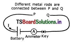
Show that the resistance of a conductor depends on the material of the conductor.
Answer:
- Collect different metal rods of the same length and same cross-sectional area like copper, aluminum, iron, etc.
- Make a circuit as shown in the figure.
- p and Q are the free ends of the conducting wires Different metal rods are connected between P and Q.
- Connect one of the metal rods between the ends P and Q.
- Switch on the circuit.
- Measure the current using the ammeter connected to the circuit and note it in your notebook.
- Repeat this with other metal rods and measure electric current In each case.
- We notice that the values of current are different for different metal rods for a constant potential differences.
- Hence, we conclude that the resistance of a conductor depends on the material of the conductor.
Activity 4
Question 5.
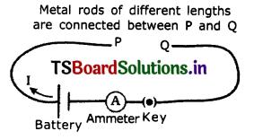
Conduct an activity to show that resistance of a conductor is proportional to the length of the conductor for constant cross-section area and temperature.
Answer:
- Collect iron spokes of different lengths with Metal rods at different lengths are connected between P and Q same cross-sectional area
- Make a circuit leaving gap between P and Q as shown in figure.
- Connect one of the Iron spokes say 10 cm long between P and Q
- Measure the value of current using ammeter connected to the circuit and note the value of current.
- Repeat this experiment for other lengths say 20cm, 30 cm, 40 cm of iron spokes and note the corresponding values of current In each case.
- We notice that the value of current decreases with increasing in the length of the iron spoke
- Thus the resistance of iron spoke increases with Increasing in the length i.e R α l
- From this we conclude that the resistance (R) of a conductor is directly proportional to its length (I) for a constant area of cross-section.
∴ R α l (at constant temperature and cross-sectional area)
Activity 6
Question 6.
Show that the resistance of a conductor is inversely proportional to its cross sectional area.
Answer:
- Collect iron rods of equal lengths but different cross-section areas.
- Make a circuit leaving gap between P and Q as shown In figure
- Connect one of the rods between P and Q and measure the current using ammeter and note values.
- Repeat this with the other rods and note the corresponding values of current in each case and note them. :
- You will notice that the current flowing through the rod increases Increase In the cross-section area of the rod.
- Thus the resistance of the rod decreases with Increase in the cross-section area. From this, we conclude that the resistance (R) of a conductor is inversely proportional to its cross-section area (A)
∴ R α \(\frac{l}{\mathrm{~A}}\) (at constant temperature and length of the conductor)
Activity 7
Question 7.
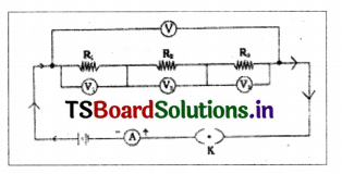
Conduct an activity to show that potential difference of combination of resistors, connected in series, is equal to sum of the P.D.S of individual resistors.
Answer:
- Connect three bulbs which act as resistors in series, with a battery, ammeter and a plug key.
- Now connect a voltmeter In the circuit across AB, close the key and note the voltage (V) across the series combination of resistors. Note the reading As V.
- Similarly connect the voltmeter across the resistors, one at a time and measure the voltage across them as V1, V2, and V3.
- You will find that V=V1 +V2 + V3
5. From this we conclude that “the potential difference across a combination of resistors, connected In serles, is equal to the sum of the voltages across the individual resistors”.
Question 8.
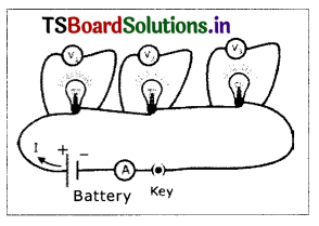
Prove that the current drawn from the battery Is equal to the sum of Individual currents drawn by the resistor, when they are connected in parrallel, with an activity.
Answer:
- Connect three bulbs which act as resistors in parallel combination (see figure).
- To this combination connect a cell ammeter and a plug key.
- Close the key and note the ammeter reading, This gives the current ‘1’ In the circuit.
- Now connect the ammeter in the branch of the circuit that has R, and note the reading. This gives the current I1 through the branch.
- Similarly, place the ammeter in the branches containing R2 and R3 and measure the currents I2, and I3 respectively.
- You will find that the current ‘I’ gets divided into the branches such that I= I1+ I2 + I3
- From this activity, we conclude that “The total Current flowing Into the parallel combination is equal to the sum of the currents passing through the individual resistors.”